
Head-specific geometry
Match the shaft to the documented multi-spindle head and its internal connection.
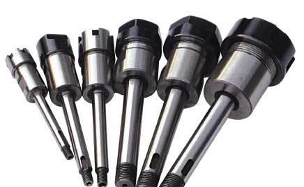
Catalog reference image. Final configuration is confirmed in the quotation.
MULTI-SPINDLE OUTPUT
Output shafts for multi-spindle drilling and tapping heads, quoted from a drawing or sample. Include connection dimensions, tool size and operating speed.
Multi-spindle head output shafts are connection-specific components for drilling or tapping heads. The company catalog shows multiple forms, so a replacement needs to be matched to the actual head rather than selected from a generic product photo. Provide the existing shaft or a complete drawing, including tool-side and head-side interfaces, to define the proposed component.
Match the shaft to the documented multi-spindle head and its internal connection.
Identify the required drilling or tapping tool interface on the output end.
Include all bearing, locating, fastening and drive features shown on the component drawing.
Start at the head side with the drive feature: show any gear, spline, keyway or coupling that actually appears on the original component. In the middle, mark the bearing and locating seats, shoulders and retaining features. At the tool end, specify the collet, chuck or other tool connection.
A matching tool-side collet size does not prove that the head-side geometry or bearing arrangement will fit. Use the head model and component drawing revision to keep these details together. Photographs should show both ends and the full side profile, with separate close-ups of worn or damaged areas.
Record dimensions from defined reference faces. Do not use a worn seat as the only source for an intended fit tolerance; identify the design requirement or request a drawing review.
State whether the inquiry is for the bare shaft or an assembled spindle with bearings, gears, seals, collet and nut. List the required items individually. A shaft photograph does not establish that every visible accessory is included.
For a tapping head, describe the holder and any axial or radial compensation arrangement separately from the shaft. Provide drilling or tapping size, workpiece material, intended speed and the inspection requirement at the tool connection. The operating limit needs confirmation for the matched assembly, not just the shaft.
Industry references: AutoDrill’s separate spindle, bearing and drive-component listings and Sugino’s tapping-head connection explanation. These illustrate why assembly details matter; they are not claims of FuRui interchangeability with those brands.
The catalog shows multiple shaft forms without a consolidated dimensional table. Final geometry must be matched to the head drawing or physical sample.
| Required order data | Accepted information |
|---|---|
| Existing shaft | Sample, photo or code |
| Dimensions | Dimensioned drawing |
| Operation | Drilling or tapping, tool size and speed |
Typical selection contexts for this series, not customer project claims. Confirm machine compatibility and cutting conditions for your setup.
Replacing or specifying an output component for a defined head assembly.
Reviewing a shaft against the tapping head's connection and operation requirements.
Producing a drawing-defined component for an agreed machine-head design.
Specify the dimensions, tolerances and records your order requires. Acceptance criteria must be agreed for the selected model.
Check the drawing reference faces and units. A catalog size alone does not define a tolerance or an inspection method.
List any required dimensional report, material document or model identification photograph in your inquiry. Confirm availability and scope in the quotation.
For a drawing-based part, include the drawing revision and identify the critical dimensions. Website photographs are not inspection reports.
Agree the packing method and photo requirements when confirming your order.
No verified shipment photographs for this series are currently published. Include selected-model, protective-packing and outer-label photos in your order requirements.
Discuss packing requirementsUse this checklist to agree what should be documented for your selected model.
Stock, dispatch date and shipping method are confirmed with the quotation. Website images are not live inventory evidence.
Keep a copy of the current series information for comparison. Confirm the final model and drawing before placing an order.
View specificationsInclude the mating interfaces, critical dimensions and quantity. Specify any required inspection or documentation in the inquiry.
OEM customizationBrowse the existing tooling guides and compare product families before selecting a model.
Browse technical resourcesCompare alternative interfaces and complementary tooling. A related series is not automatically interchangeable.

C20-C42
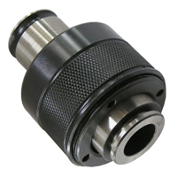
GT3 / GT12
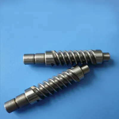
CUSTOM WORM SERIES
Provide the exact head model and shaft drawing or sample. A brand name does not define the component geometry.
No. Interfaces, locating dimensions and drive features must be confirmed.
No. Identify the exact head and tool connection, operation and holder arrangement. In particular, do not assume that tapping compensation is built into a bare output shaft; confirm where it is provided in the head-and-holder assembly.
This page covers the shaft family. Itemize any additional components required in the quotation.