
Tooth geometry definition
Specify module or DP, pressure angle, number of starts and hand as required by the drawing.
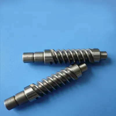
Supplier reference photo. Worm-shaft examples only; tooth geometry, journals and overall dimensions are made to a confirmed drawing.
CUSTOM WORM SERIES
Worm shafts quoted to a dimensioned drawing or sample. Include module or DP, pressure angle, number of starts, hand and shaft dimensions for technical review.
Worm shafts are drawing-based transmission components whose tooth geometry and shaft features must be matched to the intended mechanism. A complete specification includes the worm profile, starts, hand and mating requirements alongside all locating and connection dimensions. Provide the component drawing or sample so the proposed manufacturing and inspection scope can be confirmed before quotation.
Specify module or DP, pressure angle, number of starts and hand as required by the drawing.
Include all bearing seats, shoulders, threads, keyways and other drawing-defined interfaces.
Identify the mating part and the critical inspection requirements for the replacement or OEM assembly.
A worm shaft must be reviewed with the wheel it drives. Include the wheel drawing or part reference, number of teeth, centre distance and intended ratio, alongside the worm starts, hand, pressure angle and tooth-profile information.
State whether the quoted module or pitch is defined in the normal or axial plane. Equal-looking pitch numbers do not establish compatibility when their reference planes differ. The KHK worm-gear selection reference identifies hand, starts and pitch convention as mating checks. Its listed combinations do not establish interchangeability with this drawing-based product.
For a replacement, provide clear views of the tooth section, both shaft ends and bearing seats. Mark which dimensions were measured on worn surfaces and which came from the original drawing. Include the keyways, shoulders, retaining threads and any position-critical features.
A sample records the part as it is now; it may not preserve the original tooth profile or fit. Define the required material, heat treatment, inspection criteria and mating contact requirements before approving manufacture. Also identify whether the order is for the shaft alone or a reviewed worm-and-wheel pair.
See the OEM drawing-review process for the information needed to define geometry, inspection and order requirements before a quotation.
Dimensions are in millimeters unless otherwise stated. Confirm the final drawing before ordering.
| Required order data | Accepted information |
|---|---|
| Tooth geometry | Module or DP, pressure angle, starts and hand |
| Shaft | Complete dimensioned drawing |
| Inspection | Critical dimensions and report requirements |
Typical selection contexts for this series, not customer project claims. Confirm machine compatibility and cutting conditions for your setup.
Supplying a drawing-defined worm component for a specified machine mechanism.
Matching a worn shaft against the original drawing and mating-part information.
Reviewing a custom shaft as one component of an agreed transmission design.
Specify the dimensions, tolerances and records your order requires. Acceptance criteria must be agreed for the selected model.
Check the drawing reference faces and units. A catalog size alone does not define a tolerance or an inspection method.
List any required dimensional report, material document or model identification photograph in your inquiry. Confirm availability and scope in the quotation.
For a drawing-based part, include the drawing revision and identify the critical dimensions. Website photographs are not inspection reports.
Agree the packing method and photo requirements when confirming your order.
No verified shipment photographs for this series are currently published. Include selected-model, protective-packing and outer-label photos in your order requirements.
Discuss packing requirementsUse this checklist to agree what should be documented for your selected model.
Stock, dispatch date and shipping method are confirmed with the quotation. Website images are not live inventory evidence.
Keep a copy of the current series information for comparison. Confirm the final model and drawing before placing an order.
View specificationsInclude the mating interfaces, critical dimensions and quantity. Specify any required inspection or documentation in the inquiry.
OEM customizationBrowse the existing tooling guides and compare product families before selecting a model.
Browse technical resourcesCompare alternative interfaces and complementary tooling. A related series is not automatically interchangeable.
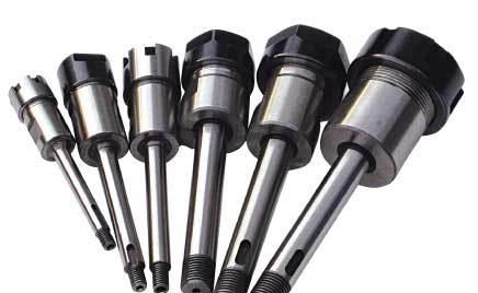
MULTI-SPINDLE OUTPUT
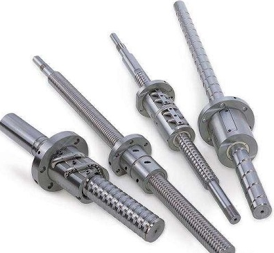
GROUND BALL SCREW SERIES
No. Include starts, hand, tooth profile, pressure angle and the module or pitch reference plane, plus shaft features and the mating wheel drawing. Wheel tooth count, centre distance and intended ratio also help define the pair. Similar diameter or a matching pitch number alone does not prove interchangeability.
A sample helps with geometry, but the original drawing and acceptance requirements are preferred, especially if the sample is worn.
Neither is established by this family listing. State the design requirements for confirmation.
Label the mating wheel or assembly reference, operating direction and the dimensions that must be preserved. Provide the original drawing if available; a worn sample should not be treated as the nominal profile or tolerance specification.