
Two catalog configurations
The listed cutter diameters are 75 and 100 mm, each with its own dimensions.
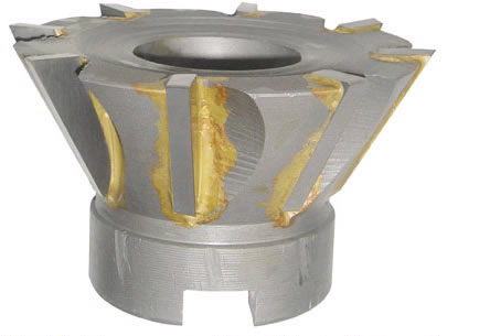
Catalog reference image. Final configuration is confirmed in the quotation.
SHELL MILL SERIES
60-degree shell carbide milling cutters in 75 and 100 mm diameters. Catalog models use 1-inch or 1 1/4-inch mounting bores, with eight or ten teeth.
The catalog's shell carbide milling cutters are listed in two configurations with a 60 degree cutting geometry and inch mounting bores. Select the cutter diameter and mounting arrangement together, then confirm the arbor's pilot, drive and fixing details. The shell cutter and arbor are separate selection items, even when their nominal bore dimensions appear to correspond.
The listed cutter diameters are 75 and 100 mm, each with its own dimensions.
The source lists 1 in and 1 1/4 in bores; retain the original units.
Confirm bore, drive and fixing geometry against the intended arbor drawing.
The catalog labels this row “60-70” but lists D = 75 mm, angle = 60°, a 1 inch bore, L1 = 28 mm, H = 50 mm and eight teeth. Use both the printed series code and the stated diameter when requesting the drawing; do not infer a 70 mm cutter from the code. The separate 60-100 row has a 1¼ inch bore.
Start an inquiry with this catalog row. State the required profile and existing arbor details. For inch-bore mounting options, compare the BT-FMA face mill arbor table, then confirm the pilot, drive and fixing dimensions. A matching nominal bore is not a complete compatibility check.
Dimensions are in millimeters unless otherwise stated. Confirm the final drawing before ordering.
Select an underlined catalog reference to include that row in your inquiry.
| Series | D | Angle | Bore d | Cutting length L1 | Height H | Z |
|---|---|---|---|---|---|---|
| 60-70 | 75 | 60 | 1 in | 28 | 50 | 8 |
| 60-100 | 100 | 60 | 1 1/4 in | 40 | 60 | 10 |
No matching model in this table. Try a shorter code, or send your required size or drawing.
Ranges and slash-separated values describe catalog families, not every possible combination. Confirm the complete model and drawing before ordering.
Typical selection contexts for this series, not customer project claims. Confirm machine compatibility and cutting conditions for your setup.
Selecting a catalog cutter and separately confirmed arbor for a milling operation.
Reviewing the stated cutting geometry against the required component shape.
Keeping inch-bore shell cutters distinct from metric pilot tooling.
Specify the dimensions, tolerances and records your order requires. Acceptance criteria must be agreed for the selected model.
Check the drawing reference faces and units. A catalog size alone does not define a tolerance or an inspection method.
List any required dimensional report, material document or model identification photograph in your inquiry. Confirm availability and scope in the quotation.
For a drawing-based part, include the drawing revision and identify the critical dimensions. Website photographs are not inspection reports.
Agree the packing method and photo requirements when confirming your order.
No verified shipment photographs for this series are currently published. Include selected-model, protective-packing and outer-label photos in your order requirements.
Discuss packing requirementsUse this checklist to agree what should be documented for your selected model.
Stock, dispatch date and shipping method are confirmed with the quotation. Website images are not live inventory evidence.
Keep a copy of the current series information for comparison. Confirm the final model and drawing before placing an order.
View specificationsSee how cutter profile and access affect a drawing-based inquiry.
Read the guideBrowse the existing tooling guides and compare product families before selecting a model.
Browse technical resourcesCompare alternative interfaces and complementary tooling. A related series is not automatically interchangeable.
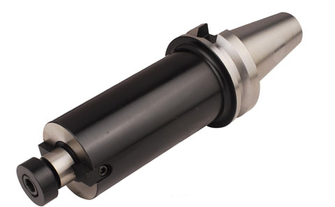
BT-FMA
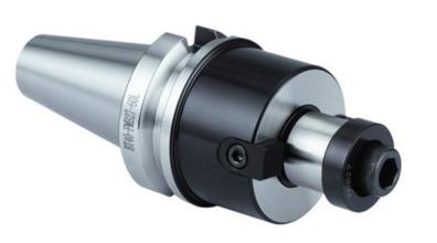
BT-FMB

HJS60-HJS200
That is how the company source records the series label and D value. Confirm the model drawing rather than correcting the code by assumption.
No. Match the exact pilot, drive features, fixing arrangement and seating geometry.
The catalog does not establish a combined package. Request the arbor separately if needed.
No. Confirm how the angle is defined and compare the full cutter geometry with the component drawing.