
Holder and chuck pairing
The source pairs G3 holders with GT3-M and G12 holders with GT12-M.
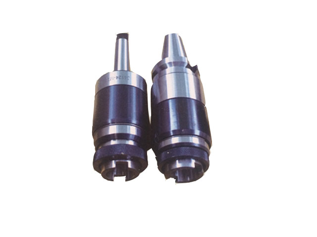
Catalog reference image. Final configuration is confirmed in the quotation.
BT-GT
BT40 and BT50 telescopic tap holders for GT3-M and GT12-M chucks. Compare M3–M12 and M12–M24 catalog ranges, connection dimensions and holder lengths.
BT GT telescopic tapping holders connect the listed BT40 or BT50 spindle interfaces to GT3-M or GT12-M tapping chucks. The catalog separates the smaller and larger tap ranges into different holder combinations. Choose the holder and chuck as a matched system, then confirm the tap shank, machine tapping method and required axial movement.
The source pairs G3 holders with GT3-M and G12 holders with GT12-M.
The listed groups are M3–M12 and M12–M24; select the correct row.
Telescopic action is identified, but the source does not state a compensation travel value.
M12 appears in both ranges, so a request for “an M12 holder” does not identify the required assembly. Include the required tap sizes, actual shank and drive-square dimensions, machine tapping method and individual chuck quantities.
The table’s L1 = 135 mm is not a stated compensation stroke. If your process requires particular axial travel, include that requirement and request confirmation against the proposed drawing. Likewise, list the chucks required separately; the holder row does not specify a complete assortment.
Compare individual GT tapping chucks or quick-change tap holder sets before finalizing the package.
Download the GT holder and chuck reference with inquiry worksheet (PDF, 3 pages)
Compare all four BT40/BT50 holder rows alongside the individual chuck models, then record each required component and quantity on the printable worksheet.
The reference separates holder dimensions from compensation requirements. Confirm the tap shank, drive square and complete mating drawing before ordering; the table does not establish compensation travel or included accessories.
Dimensions are in millimeters unless otherwise stated. Confirm the final drawing before ordering.
Select an underlined catalog reference to include that row in your inquiry.
| Ordering code | Tapping range | d | L1 | D | Chuck |
|---|---|---|---|---|---|
| BT40-G3-90 | M3-M12 | 19 | 90 | 46 | GT3-M |
| BT40-G12-135 | M12-M24 | 30 | 135 | 66 | GT12-M |
| BT50-G3-90 | M3-M12 | 19 | 90 | 46 | GT3-M |
| BT50-G12-135 | M12-M24 | 30 | 135 | 66 | GT12-M |
No matching model in this table. Try a shorter code, or send your required size or drawing.
Ranges and slash-separated values describe catalog families, not every possible combination. Confirm the complete model and drawing before ordering.
Typical selection contexts for this series, not customer project claims. Confirm machine compatibility and cutting conditions for your setup.
Building a tapping holder assembly for a documented machine cycle.
Planning matched GT chuck selections within the selected holder range.
Separating tapping holders from rigid milling and drilling holders.
Specify the dimensions, tolerances and records your order requires. Acceptance criteria must be agreed for the selected model.
Check the drawing reference faces and units. A catalog size alone does not define a tolerance or an inspection method.
List any required dimensional report, material document or model identification photograph in your inquiry. Confirm availability and scope in the quotation.
For a drawing-based part, include the drawing revision and identify the critical dimensions. Website photographs are not inspection reports.
Agree the packing method and photo requirements when confirming your order.
No verified shipment photographs for this series are currently published. Include selected-model, protective-packing and outer-label photos in your order requirements.
Discuss packing requirementsUse this checklist to agree what should be documented for your selected model.
Stock, dispatch date and shipping method are confirmed with the quotation. Website images are not live inventory evidence.
Keep a copy of the current series information for comparison. Confirm the final model and drawing before placing an order.
View specificationsIdentify the machine connection, tap shank and driving square.
Read the guideBrowse the existing tooling guides and compare product families before selecting a model.
Browse technical resourcesCompare alternative interfaces and complementary tooling. A related series is not automatically interchangeable.
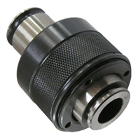
GT3 / GT12

STANDARD TAP SERIES
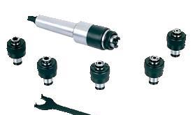
G SERIES
That is not established by the table. Specify the chucks and tap sizes required for the quotation.
No. Those are the table's L1 dimensions for the G3 and G12 holder rows, respectively. The catalog identifies telescopic holders but does not publish the compensation stroke. Do not use the 90 or 135 mm dimension as an axial-travel rating; that requirement needs the selected holder's drawing or confirmed specification.
The catalog pairs BT40-G3-90 with GT3-M chucks for M3–M12 and lists d = 19 mm and L1 = 90 mm. BT40-G12-135 is paired with GT12-M chucks for M12–M24, with d = 30 mm and L1 = 135 mm. M12 appears in both groups, so the holder connection must be identified before choosing an M12 chuck.
Also provide the tap's actual shank and driving-end dimensions, together with the tapping method.