
Asymmetric profile review
Provide the drawing's flank angles, radii and complete thread designation.

Catalog reference view. photograph and drawing.
BUTTRESS SERIES
Special buttress thread taps for one-direction load applications and confirmed profiles.
Buttress taps address a special internal-thread profile and should be ordered from a clearly defined thread drawing. The catalog identifies this family, but a product name alone does not settle flank geometry, direction or size. Include the mating-part requirements and required inspection details so the actual tool specification can be agreed before production.
Provide the drawing's flank angles, radii and complete thread designation.
State thread hand and orientation requirements explicitly for the proposed component.
Identify the critical profile and fit checks required for tool acceptance.
Source transcription for inquiry only, not a resolved ordering table. The source contains a two-column pitch field whose meaning is not explained and values that conflict with some printed designations; these pitch columns have intentionally been omitted. Repeated designations with different dimensions (rows 13/14 and 2/24) are preserved with row IDs. Every selection requires a confirmed profile drawing, pitch, handedness and tool dimensions before quotation or production.
| Catalog row | Designation as printed | Total L (mm) | Cutting length l1 (mm) | Square a (mm) | Shank d1 (mm) |
|---|---|---|---|---|---|
| 1 | B4.8×1 | 80 | 30 | 2.8 | 4 |
| 2 | B4.9×1 | 80 | 30 | 2.8 | 4 |
| 3 | B5.2×1 | 80 | 30 | 2.8 | 4 |
| 4 | B7.35×1 | 80 | 30 | 2.8 | 4 |
| 5 | B9.5×1 | 80 | 30 | 2.8 | 4 |
| 6 | B10.5×1 | 100 | 30 | 7.1 | 9 |
| 7 | B12.7×1 | 100 | 30 | 7.1 | 9 |
| 8 | B15.3×1.25 | 100 | 30 | 7.1 | 9 |
| 9 | B18.3×1.25 | 120 | 38 | 10×10 | 12.5 |
| 10 | B18.4×1.25 | 120 | 38 | 10×10 | 12.5 |
| 11 | B18.9×1.25 | 120 | 38 | 10×10 | 12.5 |
| 12 | B17.9×1.25 | 120 | 38 | 10×10 | 12.5 |
| 13 | B17.8×1.25 | 120 | 38 | 10×10 | 12.5 |
| 14 | B17.8×1.25 | 115 | 38 | 12.5×12.5 | 14 |
| 15 | B15.3×1.5 | 120 | 38 | 10×10 | 12.5 |
| 16 | B15.6×1.5 | 120 | 38 | 10×10 | 12.5 |
| 17 | B15.6×1.25 | 120 | 38 | 10×10 | 12.5 |
| 18 | B15.75×1.25 | 120 | 38 | 10×10 | 12.5 |
| 19 | B22.2×1.25 | 130 | 38 | 12.5×12.5 | 16 |
| 20 | B20.45×1.25 | 130 | 38 | 12.5×12.5 | 16 |
| 21 | B20×1.25 | 130 | 38 | 12.5×12.5 | 16 |
| 22 | B20×1.5 | 130 | 38 | 12.5×12.5 | 16 |
| 23 | B21.9×1.25 | 130 | 38 | 12.5×12.5 | 16 |
| 24 | B4.9×1 | 90 | 30 | 4.3×4.3 | 6.1 |
| 25 | B28.6×1.25 | 160 | 50 | 16×16 | 20 |
| 26 | B18×1.5 | 130 | 40 | 10×10 | 12.5 |
| 27 | B19×1.5 | 130 | 40 | 10×10 | 12.5 |
| 28 | B22×1.25 | 130 | 40 | 10×10 | 12.5 |
| 29 | B22.4×1.25 | 130 | 40 | 10×10 | 12.5 |
| 30 | B28.7×1.25 | 140 | 40 | 10×10 | 16 |
| 31 | B32.4×1.25 | 140 | 40 | 10×10 | 16 |
No matching model in this table. Try a shorter code or send us your drawing.
Ranges and slash-separated values describe catalog families, not every possible combination. Confirm the complete model and drawing before ordering.
Agree the packing method and photo requirements when confirming your order.
Verified dispatch photos for this series have not been uploaded. Request photographs of your selected model, protective packing and shipping label when confirming your order.
Discuss packing requirementsUse this checklist to agree what should be documented for your selected model.
Stock, dispatch date and shipping method are confirmed with the quotation. Website images are not live inventory evidence.
Typical selection contexts for this series, not customer project claims. Confirm machine compatibility and cutting conditions for your setup.
Producing an internal buttress profile defined by the mechanism drawing.
Reviewing tooling for parts whose designer specifies a buttress thread.
Matching a special tap against an existing tool and mating-part documentation.
Compare alternative interfaces and complementary tooling. A related series is not automatically interchangeable.

TR SERIES
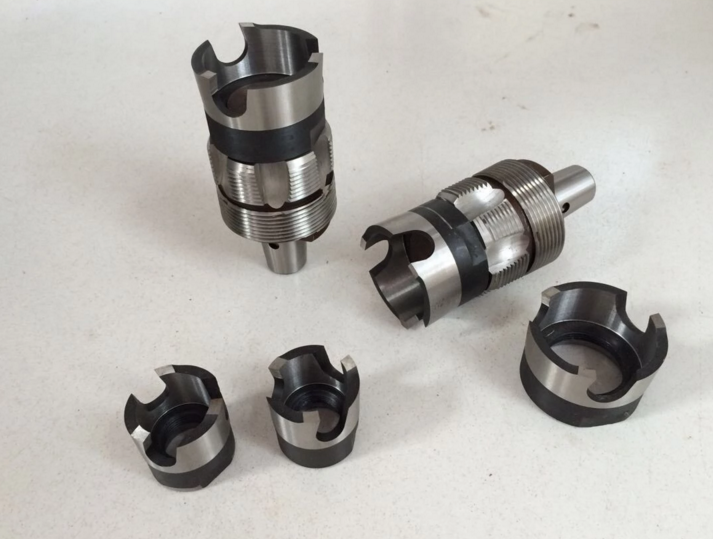
COMBINATION SERIES
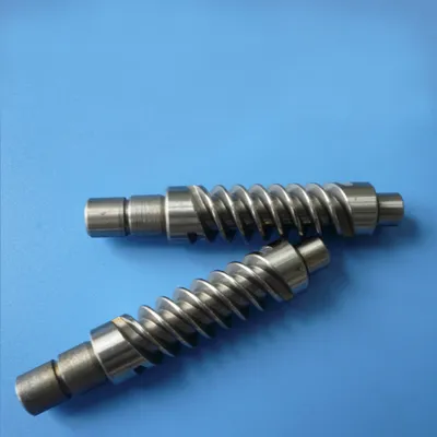
CUSTOM WORM SERIES
Provide the complete profile drawing too, including the specified flank geometry and direction.
No. The component designer must establish load capacity. This page concerns the tool needed to produce the specified thread.
Yes, include photographs and measured dimensions, but a mating-part or original tool drawing improves confirmation.
No. Treat these as distinct profiles and follow the component's exact thread requirement.