
Finished feature definition
Specify counterbore diameter, depth and any seat or step geometry.
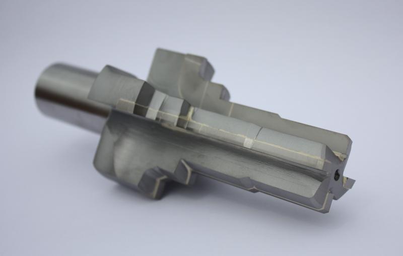
Supplier reference photo. Brazed-carbide step counterbore example; pilot, cutting diameters and connection are drawing-confirmed.
CARBIDE COUNTERBORE SERIES
Carbide counterbores and spotfacing tools quoted to the feature drawing. Include counterbore diameter and depth, pilot dimensions, shank connection and material.
Carbide counterbores and spotface tools are defined by the finished hole feature and the way the tool locates and mounts. Start with the required counterbore diameter and depth, then specify the pilot and shank or taper connection. A component drawing is especially useful where the tool must clear nearby walls or produce a special stepped feature.
Specify counterbore diameter, depth and any seat or step geometry.
Provide pilot diameter and length rather than assuming a standard pilot configuration.
Confirm the required shank or Morse taper against the actual holder.
A counterbore produces a cylindrical recess with a flat seating surface. A countersink produces a conical seat; its included angle is part of the specification. For a spotface, show the flat seating area and the permitted depth of material removal. These features should not be ordered interchangeably under a bolt-size description.
On the component drawing, mark the existing hole, finished recess diameter, depth datum and any corner-radius limit. If the seat is near a wall or inside a pocket, include that surrounding geometry so the cutter body and holder can be checked for access.
Technical terminology reference: Gühring’s countersinking and counterboring overview. This explains the feature distinction, not the dimensions or performance of the FuRui tool.
The cutting diameter defines the recess. A pilot, where specified, locates in the existing hole; the shank or taper connects the tool to the machine. Matching one diameter does not establish the other two.
For a replacement, supply a side view of the complete tool, the cutting end and the machine connection. Add the pilot diameter and length, the actual pre-hole size, workpiece material and hardness. State whether the required pilot is fixed, removable or absent rather than assuming the reference photograph establishes its construction.
The catalog does not provide a complete dimensional series for this tool. The quotation should identify the agreed cutting geometry, carbide construction and mounting drawing before an order is placed.
The company catalog introduction lists carbide counterbores without a dimensional series table. Quote against the finished feature, pilot dimensions and connection requirement.
| Required order data | Accepted information |
|---|---|
| Finished feature | Counterbore diameter and depth |
| Pilot | Pilot diameter and length |
| Connection | Shank or Morse taper requirement |
| Workpiece | Material and machining condition |
Typical selection contexts for this series, not customer project claims. Confirm machine compatibility and cutting conditions for your setup.
Producing a counterbore feature defined on a component drawing.
Creating the specified seat geometry around an existing hole.
Reviewing a stepped or restricted-access feature for drawing-based tooling.
Specify the dimensions, tolerances and records your order requires. Acceptance criteria must be agreed for the selected model.
Check the drawing reference faces and units. A catalog size alone does not define a tolerance or an inspection method.
List any required dimensional report, material document or model identification photograph in your inquiry. Confirm availability and scope in the quotation.
For a drawing-based part, include the drawing revision and identify the critical dimensions. Website photographs are not inspection reports.
Agree the packing method and photo requirements when confirming your order.
No verified shipment photographs for this series are currently published. Include selected-model, protective-packing and outer-label photos in your order requirements.
Discuss packing requirementsUse this checklist to agree what should be documented for your selected model.
Stock, dispatch date and shipping method are confirmed with the quotation. Website images are not live inventory evidence.
Keep a copy of the current series information for comparison. Confirm the final model and drawing before placing an order.
View specificationsSee how cutter profile and access affect a drawing-based inquiry.
Read the guideBrowse the existing tooling guides and compare product families before selecting a model.
Browse technical resourcesCompare alternative interfaces and complementary tooling. A related series is not automatically interchangeable.
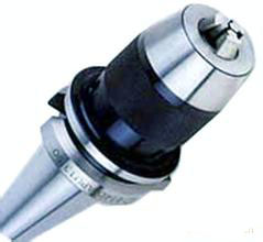
BT-SPU

YHR01-YHR08
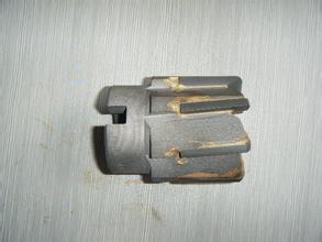
25-100 MM SERIES
No. A counterbore has a flat seating surface; a countersink has a conical seat with a specified angle. Send a section view with the diameter, depth or angle, and corner requirements so the quoted cutting geometry matches the component.
Include the actual counterbore diameter, depth and pilot requirement from the part drawing.
No fixed pilot construction is established. The proposed configuration needs confirmation.
It identifies carbide cutting edges, not a universal solid-carbide construction. Confirm the final tool specification.